Using Spatial Adjustment for Georeferencing Mosquito Point Data in ArcMap

For the Philadelphia Public Health Department, I have been asked to track mosquito trapping results through the past 17 years. The data is submitted to a state website that then testing centers upload results of tests for West Nile and Zika viruses. Luckily, every input into the state website produces and Lat Lon so when pulling the test results, I am easily able to plot the xy’s. A little more difficult of a process is getting the point set on the correct scale and in the right location as the polygon layer. Even though both layers are projected into Philadelphia State Plane South (EPSG: 2272), there is quite a big difference in location and size as you can see in the image below.


So with that, the goal is to move the point set and georeference it to Philadelphia in State Plane South Philadelphia City Limits layer.
To start this process, you need to be able to edit the point set layer, which you can’t do if you have just plotted the xy’s. You’ll need to export the data as a new shapefile. Once you’ve done that, click on Editor -> Start Editing. If you don’t see Editor, you will have to add the toolbar from the Customize drop-down menu. In Editor, you may need to select the layer you plan on editing, in this case, the point set that was just created. Next, select all points by right-clicking on the layer in the Table of Contents and pressing select all. An X will appear in the center of the points layer and you can grab the entire point set and move it closer to the Philadelphia layer. If you are unable to grab it, it’s because you have to have the editor’s cursor arrow selected like in the image below.


Now it’s time to georeference but using spatial adjustment. If you don’t see this toolbar, you need to select it in the Customize tab. Check your current coordinate system to ensure that you are in the ESPG that you want, in my case, it was 2272.

I used the information button to get the cross streets from my data set and then placed the first point for link adjust on that point. After that, I used the world geocoder service that ESRI provides as a basic geocoder to locate that area on the Philadelphia layer and click that exact location to drop the second point. This creates a line that will be used to measure the adjustment needed. The recommendation is to have at least 3 links but I use at least 4. You can see what that looks like below.


During this entire process, you want to make sure that the entire point set it selected. It is not fun to realize you left 2 points way off to the left and you have to start over. Placement of your links are vital to the success of your adjustment. Be sure to scatter them.


Once you’ve created at least 3 links, click the spatial adjustment drop-down menu and click Adjust. It is as easy as that. Here is the final point set. Make sure to save all your edits in Editor!


Updating Addresses and Adding New LandCare Sites for PHS

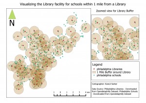
During sprint two of my capstone with PHS, I worked on finishing the update structure for LandCare Project shapefiles. As we were updating both parcels and sites, code was required for each subset of data. To streamline the process, I used metacoding like what was posted in my first blog post. There were two main processes that were coded in this sprint: address updates and the addition of whole new sites. Both will be discussed in this blog post.

I have found it best when explaining the parts of this project to think about parcels and sites as Lego bricks and structures respectively. Consider an individual Lego brick. Singularly it does a job and has a function, just as a land parcel does as a singular address. But, when parcels are added together they become sites that consist of multiple addresses. This could be considered to when several Lego bricks are combined to make a structure. There is still the ability to remove or add bricks but the overall geometry of the structure will change.

This is comparable to the address addition and removal process. As we add a new parcel or brick, we must also update the sites file as the geometry is changing. This is also true for the removal of a parcel. While the changes we are making may include only the addition of one small parcel or brick, the site geometry or structure changes significantly. This requires a special geometry update in SQL to ensure that these changes are not missed accidentally in a shapefile update.

These address updates were broken into two separate metacoding files: address addition and address removal. Address addition utilized data for parcels from the Philadelphia Water Department to provide geometries for new parcels being added to sites. Each parcel was individually added to the parcels file first with the selection of the geometry and other unique fields from the PWD parcel data. Following, data was updated for the parcel file for the new address range. Other parcel information was copied from other parcels in the site we were interested in. The code for these parts has been pasted below.

INSERT INTO PLCmaint_parcels_2017 (ADDRESS, Geometry)
SELECT ADDRESS, Shape
FROM allparcels_517
WHERE ADDRESS = "1501 N 15TH ST";

UPDATE PLCmaint_parcels_2017
SET PARCELID = (SELECT PLCmaint_parcels_2017.PARCELID FROM PLCmaint_parcels_2017 WHERE PLCmaint_parcels_2017.ADDRESS = "1503 N 15TH ST"),
    TENCODE = (SELECT PLCmaint_parcels_2017.TENCODE FROM PLCmaint_parcels_2017 WHERE PLCmaint_parcels_2017.ADDRESS = "1503 N 15TH ST"),
    OWNER1 = (SELECT PLCmaint_parcels_2017.OWNER1 FROM PLCmaint_parcels_2017 WHERE PLCmaint_parcels_2017.ADDRESS = "1503 N 15TH ST"), 
    OWNER2 = (SELECT PLCmaint_parcels_2017.OWNER2 FROM PLCmaint_parcels_2017 WHERE PLCmaint_parcels_2017.ADDRESS = "1503 N 15TH ST"),
    BLDG_CODE = (SELECT PLCmaint_parcels_2017.BLDG_CODE FROM PLCmaint_parcels_2017 WHERE PLCmaint_parcels_2017.ADDRESS = "1503 N 15TH ST"),
    BLDG_DESC = (SELECT PLCmaint_parcels_2017.BLDG_DESC FROM PLCmaint_parcels_2017 WHERE PLCmaint_parcels_2017.ADDRESS = "1503 N 15TH ST"),
    BRT_ID = (SELECT PLCmaint_parcels_2017.BRT_ID FROM PLCmaint_parcels_2017 WHERE PLCmaint_parcels_2017.ADDRESS = "1503 N 15TH ST"),
    GROSS_AREA = (SELECT PLCmaint_parcels_2017.GROSS_AREA FROM PLCmaint_parcels_2017 WHERE PLCmaint_parcels_2017.ADDRESS = "1503 N 15TH ST"),
    Shape_Area = (SELECT PLCmaint_parcels_2017.Shape_Area FROM PLCmaint_parcels_2017 WHERE PLCmaint_parcels_2017.ADDRESS = "1503 N 15TH ST"),
    PID = (SELECT PLCmaint_parcels_2017.PID FROM PLCmaint_parcels_2017 WHERE PLCmaint_parcels_2017.ADDRESS = "1503 N 15TH ST"),
    Year = (SELECT PLCmaint_parcels_2017.Year FROM PLCmaint_parcels_2017 WHERE PLCmaint_parcels_2017.ADDRESS = "1503 N 15TH ST"),
    Season = (SELECT PLCmaint_parcels_2017.Season FROM PLCmaint_parcels_2017 WHERE PLCmaint_parcels_2017.ADDRESS = "1503 N 15TH ST"),
    VL_Num = (SELECT PLCmaint_parcels_2017.VL_Num FROM PLCmaint_parcels_2017 WHERE PLCmaint_parcels_2017.ADDRESS = "1503 N 15TH ST"),
    Sq_Ft = (SELECT PLCmaint_parcels_2017.Sq_Ft FROM PLCmaint_parcels_2017 WHERE PLCmaint_parcels_2017.ADDRESS = "1503 N 15TH ST"),
    Trees_Num = (SELECT PLCmaint_parcels_2017.Trees_Num FROM PLCmaint_parcels_2017 WHERE PLCmaint_parcels_2017.ADDRESS = "1503 N 15TH ST"),
    TARGETAREA = (SELECT PLCmaint_parcels_2017.TARGETAREA FROM PLCmaint_parcels_2017 WHERE PLCmaint_parcels_2017.ADDRESS = "1503 N 15TH ST"),
    Grid = (SELECT PLCmaint_parcels_2017.Grid FROM PLCmaint_parcels_2017 WHERE PLCmaint_parcels_2017.ADDRESS = "1503 N 15TH ST"),
    CCD = (SELECT PLCmaint_parcels_2017.CCD FROM PLCmaint_parcels_2017 WHERE PLCmaint_parcels_2017.ADDRESS = "1503 N 15TH ST"),
    ZIPCODE = (SELECT PLCmaint_parcels_2017.ZIPCODE FROM PLCmaint_parcels_2017 WHERE PLCmaint_parcels_2017.ADDRESS = "1503 N 15TH ST"),
    Action = (SELECT PLCmaint_parcels_2017.Action FROM PLCmaint_parcels_2017 WHERE PLCmaint_parcels_2017.ADDRESS = "1503 N 15TH ST"),
    TARG_GRID = (SELECT PLCmaint_parcels_2017.TARG_GRID FROM PLCmaint_parcels_2017 WHERE PLCmaint_parcels_2017.ADDRESS = "1503 N 15TH ST"),
    CCD_Person = (SELECT PLCmaint_parcels_2017.CCD_Person FROM PLCmaint_parcels_2017 WHERE PLCmaint_parcels_2017.ADDRESS = "1503 N 15TH ST"),
    Program = (SELECT PLCmaint_parcels_2017.Program FROM PLCmaint_parcels_2017 WHERE PLCmaint_parcels_2017.ADDRESS = "1503 N 15TH ST") 
WHERE ADDRESS IN (
                SELECT ADDRESS
                FROM PLCmaint_parcels_2017
                WHERE PLCmaint_parcels_2017.ADDRESS = "1501 N 15TH ST");

UPDATE PLCmaint_parcels_2017
SET NumParcels = "13",
    Addr_Range = "1501 - 1507 N 15TH ST"
WHERE VL_Num = "VL0123EN_CLP";

Once parcel information was added and correct, the site shapefile geometry was updated accordingly. This was the product of a ST_Union function that inserted new geometries into the sites table in SpatiaLite. Address ranges and parcel numbers were updated accordingly as shown in the code block below.

UPDATE PLCmaint_SITES_2017
SET Geometry = (
                SELECT ST_Union(Geomtery)
                FROM PLCmaint_parcels_2017
                GROUP BY VL_Num);

UPDATE PLCmaint_SITES_2017
SET NumParcels = "13",
    Addr_Range = "1501 - 1507 N 15TH ST"
WHERE VL_Num = "VL0123EN_CLP";

Parcel removal required the copy of parcel data first to the New Use table so changes would be documented for the future. Once this was done, the parcel was deleted from the parcel table. The site geometry was updated following the same process as previously. Address ranges and parcel numbers were updated accordingly. This code can be visualized below for reference.

INSERT INTO NewUse_2017 (PARCELID, TENCODE, ADDRESS, OWNER1, OWNER2, BLDG_CODE, BLDG_DESC, BRT_ID, GROSS_AREA,
    Shape_Area,VL_Num, Sq_Ft, Trees_Num, PID, TARGETAREA, Grid, CCD, Addr_Range, ZIPCODE, Geometry)
SELECT PARCELID, TENCODE, ADDRESS, OWNER1, OWNER2, BLDG_CODE, BLDG_DESC, BRT_ID, GROSS_AREA, Shape_Area, VL_Num, 
    Sq_Ft, Trees_Num, PID, TARGETAREA, GRID, CCD, Addr_Range, ZIPCODE, Geometry
FROM PLCmaint_parcels_2017
WHERE ADDRESS = "1501 N 15TH ST";

DELETE FROM PLCmaint_parcels_2017
WHERE ADDRESS = "1501 N 15TH ST";

UPDATE PLCmaint_parcels_2017
SET NumParcels = "12",
    Addr_Range = "1503-1507 N 15TH ST"
WHERE VL_Num = "VL0123EN_CLP";

UPDATE PLCmaint_SITES_2017
SET Geometry = (
                SELECT ST_Union(Geometry)
                FROM PLCmaint_parcels_2017
                GROUP BY VL_Num);

UPDATE PLCmaint_SITES_2017
SET NumParcels = "12",
    Addr_Range = "1503-1507 N 15TH ST"
WHERE VL_Num = "VL0123EN_CLP";

Adding new sites entirely was a straightforward process. Four sections of metacoding were used to break down information and explain steps. The data was copied from provided shapefiles into the parcels table first, then the sites.

For the sites table update, the VL numbers (unique parcel identifier) were selected with a “SELECT DISTINCT” statement and these were copied into part three. This allowed for only the information for one parcel to be copied into the sites table, representing the data for the site that was available. Finally the site geometry was updated using the ST_Union feature described above. The code used is visible below.

INSERT INTO PLCmaint_parcels_2017 (PARCELID, TENCODE, ADDRESS, OWNER1, OWNER2, BLDG_CODE, BLDG_DESC, BRT_ID, 
    GROSS_AREA, Shape_Area, Year, Season, VL_Num, NumParcels, Sq_Ft, Trees_Num, TARGETAREA, Addr_Range, Geometry)
SELECT PARCELID, TENCODE, ADDRESS, OWNER1, OWNER2, BLDG_CODE, BLDG_DESC, BRT_ID, GROSS_AREA,Shape_Area, Year, 
    Season, VL_Num, NumParcels, Sq_Ft, Trees_Num, TARGETAREA, Addr_Range, Geometry)
FROM Fall16_Stabilization_parcels;

SELECT DISTINCT VL_Num
FROM Fall16_Stabilization_parcels;

INSERT INTO PLCmaint_SITES_2017 (VL_Num, ADDRESS, Year, Season, NumParcels,  Sq_Ft, Trees_Num, TARGETAREA, Addr_Range, Geometry)
SELECT VL_Num, ADDRESS, Year, Season, NumParcels,  Sq_Ft, Trees_Num, TARGETAREA, Addr_Range, Geometry
FROM Fall16_Stabilization_parcelsGROUP BY VL_Num HAVING VL_Num = "VL0123EN_CLP";

UPDATE PLCmaint_SITES_2017
SET Geometry = (
                SELECT ST_Union(Geometry)
                FROM PLCmaint_parcels_2017
                GROUP BY VL_Num);

Any resulting data from these sections were queried to double check the work. My sprint three blog will cover the exporting of these tables to shapefiles and will use visualizations.

Using Metacoding for Philadelphia LandCare Site Manipulation

For my capstone project, I will be working with Pennsylvania Horticulture Society to develop a streamlined data management system for their LandCare Program. The LandCare Program strives to rehabilitate vacant land parcels in the city of Philadelphia to address urban revitalization and land vacancy issues plaguing the city. The image below shows what some of these land areas can look like.

The project has so far consisted of the construction of a database in SpatiaLite to work with the shapefiles for the project, see the image below for an overview of the GUI. I selected SpatiaLite as it uses the SQLite language and connects seamlessly with ArcMap. This ultimately allows the user to create an manipulate geodatabases using code written in SpatiaLite and immediately access the results in ArcMap.

My first sprint (May 30th to June 8th) consisted primarily in the set up of documentation for the project, in addition to the following items: creating a geodatabase, working to remove sites that have new uses (no longer PHS LandCare sites) as well as writing base code for updating tables based on an excel.

The process to create documentation was decided upon so formal directions would be available for anyone working on this project in the future. In addition to this, I have detailed notes of what I have done thus far and can change information as the project progresses.

Most of the coding that has been done thus far has been metacoded in excel. By doing this, the overall update process is now streamlined to where someone with no SQL experience can use the excel and get valid results. Using the image below, an example to delete a row from a table in SpatiaLite, it is visible that the user only must input a small amount of information such as the table name and the identifier for the row being deleted. This will benefit not only the inexperienced coder in the future, but also anyone who must update many files at once as only one column must be manipulated. The end result will be to gain statements that can be copied and pasted in the query window of SpatiaLite.

So far, there are metacoding files for updating new use sites and updating columns overall. When updating new use sites, we must copy information from both parcels (individual lots) and sites (many lots together) to develop one overarching row of data. This process was broken down into four steps, two with updates and two for deleting the land area from the new parcel and site tables as they are no longer in the maintenance database. The individual update metacoding was created for a quick update like square feet. Using this process, much information can be quickly added to the pre-written code and then executed in SpatiaLite.

Finally, in sprint two, the next process will be determining the process to update parcel and site data for address changes. As many sites may lose a parcel or gain a parcel over the course of the year for maintenance purposes, it is important that adequate files are maintained on current geometries. This will most likely be completed again with many steps in the form of a metacoded file.

Find the best matched polygons for use in a time series using pgAdmin

Goal:
Find the best matched polygons in a time series using a PostGIS Spatial Database
Background:
For previous project a comparison of housing data from the 1930s to current and historic US Census data was required. The geographic portion of the census data, was obtained from the National Historical Geographic Information System (NHGIS) which produces downloadable shapefiles with a GISJOIN field allowing for convenient linking of the shapefile to tables of census data also available through NHGIS. The 1930s housing data was in the form of an image of a 1937 Home Owners’ Loan Corporation (HOLC) map of Philadelphia available here. Very broadly the HOLC graded neighborhoods based on race/class and these grades where then used to determine the likelihood of housing loan assistance. There is debate if the HOLC process normalized race-based home lending practices and then the lead to further housing issues such as redlining. more info.

Process:
The HOLC map data was pulled into a GIS and a shapefile was created of the neighborhood grading (this process is often listed as ‘Heads-up Digitizing’ in job postings) here is a handy tutorial for ArcMap and another using QGIS. Shapefile and HOLC jpeg available on github.

The HOLC neighborhood grading schema does not coincide with any current (or historic) census arrangement so the spatial querying capabilities of pgAdmin and the PostgreSQL database engine was used to match the newly created HOLC digital data with the NHGIS Decennial Census geographic data.
Create a PostGIS Spatial Database and use pgShapeLoader to load the shapefiles (HOLC and NHGIS spatial data)

After much trial and error the following code worked the best:

create table overlap2010census as
with limited as(
select distinct us2010.*
from us2010, holc1937
WHERE ST_DWithin(us2010.geom, holc1937.geom, 0.25)
order by us2010.gid
)
/* the section above limits the query of the 2010 census polygons (Entire US) to those near the HOLC polygons –input can vary based on projection of files*/

SELECT DISTINCT ON (limited.gid)
limited.gid as us2010a_gid,
holc1937.gid as holc_gid, holc1937.name, holc1937.grade,
st_area((st_transform(limited.geom,4326)::geography)) as area_check,
ST_Area(ST_Intersection((st_transform(limited.geom,4326)::geography),
(st_transform(holc1937.geom,4326)::geography))) as intersect_area_2010_meters,
(ST_Area(ST_Intersection((st_transform(limited.geom,4326)::geography),
(st_transform(holc1937.geom,4326)::geography)))/
st_area((st_transform(limited.geom,4326)::geography)))*100 as percent_overlap,

/*calculates the area of the returned census and HOLC polygons and the percent of overlap */

limited.*
FROM limited, holc1937
where limited.geom && ST_Expand(holc1937.geom,1) and ST_Area(ST_Intersection(limited.geom, holc1937.geom)) >0

/* joins the files where the geom overlap*/

ORDER BY limited.gid, ST_Area(ST_Intersection((st_transform(limited.geom,4326)::geography),
(st_transform(holc1937.geom,4326)::geography))) DESC;

/* sorts by the largest amount of overlap, and in conjunction with the DISTINCT ON call
only returns the first instance of the census polygon that overlaps the target polygon */

While this method requires the user to update and repeat this code for each comparison the tables created can then be exported out to your GIS or QGIS can connect directly to your database if you prefer that option. As the query also created a unique identifier for each year and polygon of the Census data, a crosswalk/key table was created using this data which allowed for the Census data (race,income housing status etc.) for multiple years to be attached via the NHGIS GISJOIN field previously mentioned. Based off of the multiyear Census data attached via the crosswalk table comparisons of the HOLC geographic areas could then be made regardless of shifting Census borders.

Courses Offered Fall 2017

The following courses are being offered Fall 2017. All times are 5:30pm to 8pm. Please refer to Banner for more information.

Monday

  • GUS 5062 – Fundamentals of GIS
  • GUS 8065 – Cartographic Design (required)

Tuesday

  • GUS 5062 – Fundamentals of GIS
  • GUS 5065 – Urban GIS (elective)
  • GUS 5069 – GIS for Health Data Analysis (elective)
  • GUS 5161 – Statistics for Urban Spatial Analysis

Wednesday

  • GUS 8067 – Spatial Database Design (required)

Thursday

  • GUS 5063 – Remote Sensing (elective)
  • GUS 5068 – Census Analysis with GIS (elective)

Friday

  • GUS 9187 – GIS Capstone (required, does not meet every week)

Determine crimes between schools and Public Libraries

There are about 550 schools and total 55 public libraries in Philadelphia. From all US small and largest cities, Philadelphia has one of the highest crime rate (44 per one thousand). This project tries to determine the risk for students when they want to go to the nearest public library. It also determines how many schools are in one mile from each library that will show how the libraries are unevenly distributed into the city area or the public libraries did not consider the number of schools around it when they established. This also shows where the schools and library and how many crimes happened around each school and library. So, this will predict the possibility to become a victim with the neighborhood crimes. To do this, I have used PostgreSQL which is easier to calculate and measure the risk on the way from a school to a closest library.

I used three important data sources such as school data as .csv, library data as a shapefile and the crime data that shows all the reported crimes that happened in Philadelphia from 2007 to 2014. All these data are acquired from OpenDataPhilly which is a open data source. After download all the necessary data performed a data normalization to reduce the data redundancy. To use these data with PostgreSQL, need to upload in the SQL server (for the shapefile use the shp2pgsql command and for the .csv file use the simple SQL console). The map below shows the location of schools and libraries,  crime incidences around one mile of each schools  and the numbers of schools within one miles from each public libraries.

1 mile_librarySchool Buffer

After applying some quarries, I have found that there many schools where more than 2000 crimes happened and there are three schools where more than 5000 crimes happened within 1000 feet, and there are 5 libraries where more than 2000 crimes happened in those 7 years. The libraries are unevenly distributed around the city depending on the number of schools. There some libraries in which there are only one school, and there are two libraries where more than 20 schools within one mile. Even there are some schools that are more than one and half miles away from the closest libraries. The figure below shows the lines between the schools and the closest libraries with hundred feet buffer around the lines.


CREATE TABLE phl.shortest_distance_buffer AS
SELECT e.from_school, e.close_library, ST_Buffer(geom,100)::geometry(Polygon,2272) AS geom
FROM (
SELECT d.school as from_school,
d.library as close_library,
ST_MakeLine(d.geom1, d.geom2) as geom
FROM(
SELECT
s.facil_name AS school,
s.geom AS geom1,
A.branch_nam AS library,
A.geom AS geom2,
ST_Distance(s.geom, A.geom) as distance
FROM
phl.all_philly_school as s
CROSS JOIN LATERAL
(
SELECT l.branch_nam, l.geom
FROM phl.philly_libraries as l
ORDER BY l.geom s.geom
LIMIT 1
) AS A) as d) as e;


SELECT a.from_school, a.close_library, count(b.objectid)
FROM phl.shortest_distance_buffer as a
JOIN phl.philly_crime_incident_coded as b
ON ST_Contains(a.geom, b.geom)
GROUP BY a.from_school, a.close_library
ORDER BY count(b.objectid);

The above queries, I have use to make a straight line between each school to the closest libraries and make a 100 feet buffer around the each line. The bottom part of the query count crimes in each buffer. The intention of doing this is to determine the number of crimes happen in each buffer line and to find out the possibility to become victim if a student want to go to the closest library from school. The result of this query shows that there are 14 line distance from schools and libraries where more than 650 crime happen  from 2007 to 2014. Therefore, it is more likely to become a victim with the neighborhood crimes than other 531 line distances from schools to libraries. Alternatively, there are 12 line distances between schools and closest libraries where less than 10 crimes happen from 2007 to 2014.

There are some limitations in the project like the straight lines that created between schools and closest libraries are not the route to get to a library, so, the crime calculations are not right just an assumption. Also, at the time of crime calculation I did not concern the time of crime, and the student’s intending time to go to a library. It is important to consider the time of crime and the intending time for a student to go to a library to make a rational estimate of crimes (including the type of crime) that happen into the buffer areas. Depending on the limitations, the further research can be done in which the researcher can use the PG Routing to get the exact routes with distance between a school and a closest library and connect that result with the crimes considering the time and type of crimes to make an potential report to see the possibilities of becoming a victim by a neighborhood crime when a student intended to go to a library. The research can also find the alternative routes and day time where and when (safest way and time) has very less possibilities to become a victim by the neighborhood crime.


For project detail contact email: kamol.sarker@temple.edu

First Look at the New Indoor CAD to GIS Tool

To continue my series discussing CAD to GIS integration, I will look at ESRI’s new Indoor CAD to GIS Tool.  This tool is included with the newest update to ArcGIS Desktop 10.5 or ArcGIS Pro 10.4 and requires Microsoft Excel or LibreOffice/OpenOffice.  The tool was designed to conform to the American Institute of Architects (AIA) specifications for indoor spaces and is part of ESRI’s new collection of CampusViewerTools.

Where you need to specify which CAD layer is floor plan line, interior space, or identifier.

The tool uses an .xlsx worksheet with three tabs for the CAD Data.  The CAD LAYER TO FC MAPPING tab is where you manually separate all CAD layers as either Floor Plan Lines, Interior Spaces, or Identifiers.  The Building Properties Tab is where general building information such as Building Name or Date Built is stored to be included with all data imported.  The Floor Properties tab is where you identify the floors of the CAD layer and set the order, elevation, and ceiling heights for each floor- which is necessary if you plan on incorporating these into a 3D GIS.

Running the tool in ArcGIS- very simple to use and most of the fields auto-populate when you open it.

Once the .xlsx worksheet is complete, you save it as a .csv so can be used in ArcGIS. Once in ArcGIS, you open navigate to the tool using your Catalog and much of the import is already auto-populated.  Just locate your .gdb to save it to and the spatial reference and run the tool.  When it’s done, you’ll see the gdb now has your building footprint, floor footprint, floor plan lines, and interior spaces ready to use.

The resulting floor plan- looks great!

Ultimately, the new Indoor CAD to GIS Tool is very easy use and has great results.  As I’ve discussed in several posts, CAD to GIS conversion can be very messy and time-consuming, and the new Indoor CAD to GIS Tool is now an essential tool when doing this work.

It does have several limitations, being it requires your CAD data to have consistent layer naming and be in a real-world coordinate system.  If you are working with an entire campus of data that has a variety of layer naming standards and no coordinate system, it will take you several steps to even begin using this tool.  However, assigning a coordinate system and renaming layers within a consistent standard between drawings can both be accomplished using a Python script or a LISP script in AutoCAD.

The tool runs pretty slow (one building with 3 floors took just under 10 minutes) and any typo at any point in the spreadsheet can lead to the tool not working.  While it takes a while to populate the spreadsheets, it is still much quicker than manually importing the CAD files and cleaning them up one-by-one.

More info on the new Indoor CAD to GIS tool can be found HERE.

Land Classification and Land Use

After the completion of my Geo-referencing tasks (years 1995, 1975, and 1959), I was given the option between more Geo-referencing (1965) or a slightly different route, which consisted of creating a method to classify land types and land uses. If it wasn’t obvious by the title, I chose Geo-referencing 1965…

Land classification is the method of determining what a feature is on imagery purely based on pixel value (pixel value can be interpreted differently depending on the situation). This allows for a colorful rendition and separation, which results in an easy to read and visualize context of where different features are located. Results can vary and are heavily reliant on image quality. The lower quality the image or imagery, the more generalization and inaccuracy of the classifications.

Anyway, land classification can be simple and it can also be quite difficult. If you are using tools that already exist, or software that are built to classify imagery, you can easily begin land classification/land use. If you are using preexisting material it will quickly become a matter of finding the right combination of numbers in order to get the classifications you want. This method is not too difficult, just more tedious in regards to acquiring your result. However, if you approach it from scratch, it will be significantly more engaging. In order to approach it from the bottom up, you have to essentially dissect the process. You have to analyze your imagery, extract pixel values, group the pixel values, combine all of them into a single file, and finally symbolize them based on attribution or pixel value which was recorded earlier. It is much easier said than done.

I am currently approaching the task via already created tools, however if I had a choice in the matter, I would have approached it via the bottom up method and attempted to create it from scratch as there is more learning in that and it is much more appealing to me. Regardless, I am creating info files, or files that contain the numbers, ranges, and classifications I am using to determine good land classifications. In contrast to what I stated earlier, this is quite difficult for me as the imagery is low quality and I am not a fan of continuously typing in ranges until I thread the needle.

The current tool I am using is the reclassify tool that is available through the ESRI suite and it requires the Spatial Analyst extension. This tool allows for the input of a single image, ranges you would like to use to classify the selected image, and output file. After much testing, I am pretty sure there can only be a maximum of 24 classifications (which is probably more than enough). In addition, the tool can be batch ran (as most ESRI tools can be), which means it can be run on multiple images at once. This is a much needed features for many situations, as I presume most times, individuals are not going to classify one image and be done (or at least I am not going to be one and done).

That is an image that was reclassified using the reclassify tool. I am not sure how good of a classification this is as I have not fully grasped the tool yet and every time I give it ranges, it spits out the same generic ranges that I did not input (which is a bit frustrating, but it comes with the territory). I am sure it is human error though and not the tool messing up. I am not sure what the final result is supposed to be, but I will be sure to fill you in once I achieve it (if I ever do…).

Creating a Network Analysis Dataset and Generating a Service Area Layer

Network analysis can be an extremely beneficial tool for any organization which relies on GIS to understand the area it serves. This is particularly true if the organization deals primarily with transportation or the distribution of goods. The network analysis package through ArcGIS allows organizations to gain critical insight into how people and goods move around within their designated service or study area. More specifically, the engineers that I work with at McMahon utilize GIS network analysis to gain enhanced insight on the regions in which they serve as transportation engineers and planners. The baseline method of analysis utilized is creating a service area layer, or series of layers, to gain an understanding of how much distance can be traveled on a road network given a set of parameters.

A Basic Example of a Service Area Layer, With Three Interval Breaks

The first step in creating a service area layer is to create a network dataset. A network dataset is a special type of ESRI dataset, which contains both spatial layers and network layers, as well as custom preferences and parameters to fine tune the output of the network dataset. To create a network dataset, first, download a road network layer that represents the area in which you want to create service areas. Often times, these layers are available from government agencies. For example, all Pennsylvania state and local roads are available on PASDA, provided by PennDOT. Once the streets / roads layer is downloaded, it is important to clip the layer to what you expect you might utilize from the service area analysis. If you choose not to clip the layer, you may find creating and working with the network dataset to be slow and difficult to manage.

You will also need to create a source point file that will represent the location or locations from which the service areas will be generated. You can create the actual points either now or after the network dataset is created, but the point feature class itself needs to be created beforehand. You will also need to create a file geodatabase and feature dataset to store all of these layers and datasets in.

Once the layer is downloaded, clipped, and present in your working directory with the source point file you can create the network dataset. This can be done by right-clicking inside any feature dataset and clicking new > network dataset. A dialog window should appear with options regarding the new network dataset. Name the network dataset and click next. You can leave most of the settings at their default values unless otherwise instructed or if you know the network dataset will be used for purposes in addition to creating a service area. Finally, on the second to last page of options, check the box next to “build service area indexes”. This will speed up the creation of service areas in the future.

Creating a New Network Dataset Inside of a Feature Dataset

Click finish, and you will be asked if you want to build the network dataset. Click Yes. Once the network dataset has been created, open ArcMap and bring the newly created network dataset into the dataframe. When prompted to bring in any associated layers, say yes. Add the Network Analyst toolbar and click “New Service Area” under the Network Analyst dropdown.

Creating a New Service Area with Network Analyst

Click the button directly to the right of the Network Analyst dropdown, to open Network Analyst Window. Here, you can load any origin points (previously created), polygon or line barriers, as well as set options for the service area that is going to be created. You can drag the point layer which contains the origin points into the Facilities group. Clicking the Service Area Properties button (top right corner of the Network Analyst Window) will allow you to set important preferences for the service area that is about to be created. Some of the most useful settings include the accumulation tab, which allows you to track distance and time along the service area, and the analysis settings tab. The analysis settings tab will allow you to set the direction of the service area, as well as any breaks, and to implement a temporal aspect to the service area.

Service Area Properties

Apply any preferences and settings that have changed, and close the service area properties window. When everything is configured as desired, click the Solve button on the network analyst toolbar to run the analysis and create the service area. The analysis can be re-run an infinite number of times, and with the service area index that was created earlier, creating a service area should not take long each time. This way, you can tweak and fine tune the service area quickly and easily until you gain the desired result.

A Service Area Created Using Network Analyst