Georeferencing Floor Plans for Use in GIS

ArcGIS claims to have seamless integration between CAD and GIS.  However, this integration can be very confusing if your CAD floor plans are not georeferenced already.  Furthermore, the Georefencing toolbar in ArcGIS can be very time consuming to manually shift, rotate, and scale each floor plan one-by-one.   This post will look at an efficient way to georeference floor plans by building using the AutoCAD World File tool.

First, you would need to download the AutoCAD World File from this link.  This tool contains a .LSP script that will assign a world file to each .dwg file.  A world file contains the locations reference points in order for the GIS software to know where to place each floor plan when it is brought into the GIS software.


Step One: Export a shapefile to CAD

Right click on the shapefile of the buildings that contain the floor plans and select Data-> Export to CAD.  Next, export that shapefile in the DWG2013 format.  Leave the selection and seed file as they are.


Step Two: Open the shapefile CAD

To do this, just open the .dwg file in the folder that it was saved in.  Once you open this file, you will notice it looks just like it would in GIS.  Furthermore, the coordinates are included at the bottom of the document showing that you are now working in a georeferenced plane.


Step Three:  Add the Floor Plan 

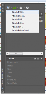
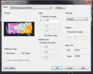
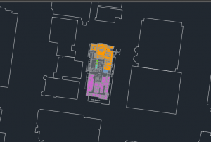
Type the command XREF in the bottom command bar and hit enter.  This will open a file reference box.  Open the drop-down menu under the DWG icon and select DWG.  Navigate to a floor plan you want to add and select it.  In the following window, under Scale de-select “Specify on Screen” and select Uniform Scale.  Enter 1/12 in the X box in order to convert feet to inches to scale the floor plans correctly.  Select “Specify On Screen” for Insertion Point and Rotation and leave Reference Type as “Overlay”.  Click OK.

Select the point of insertion and rotation angle in order to place the floor plan.  Don’t worry if it isn’t exact because you can adjust it quite easily.


Step Four: Align Floor Plan

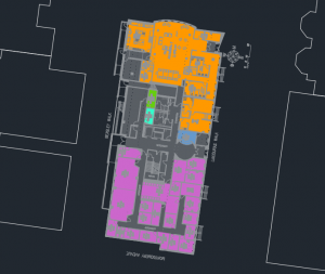
In order to adjust the floor plan so it aligns with the building footprint, type the command ALIGN in the command box.  Select your floor plan and hit enter.  Next, you will be instructed to select a minimum of two reference points.  Match up opposite corners of the floor plan to the building foot print.  I suggest you use more than two reference points to accomplish this.  You can do the ALIGN operation as many times as needed to get the floor plan precisely aligned to the footprint.


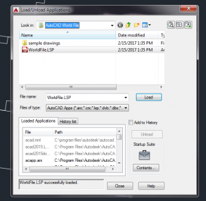
Step Five: Activate the AutoCAD World File App

Type APPLOAD command into the command bar and locate the AutoCAD World File folder.  Select the WorldFile.LSP file and hit Load.  Wait for the box on the bottom to say “World File Loaded Successfully” and then hit close.


Step Six: Using the Tool to Create a World File

Type CREATEWORLDFILE command in the command bar and hit enter.  Select the floor plan (not the footprint!).  A Save File box will open with a file name esri_cad.wld.  Locate the folder that contains all the buildings floor plans and hit save.  Do not change the name of the .wld file.


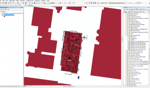
Step Seven: Open the CAD Drawing in ArcGIS

Open the same shapefile you used in this demo in ArcGIS.  Use the Catalog to navigate to where the building floor plans you just created a world file for is located.  Drag the floor plan file into the GIS window.  Now, the floor plan should drop right on top of the building footprint.


Notes:

This demo should work for all floor plans for the building.  However, in many buildings floors are not always the same size so the georeferencing may need to be tweaked to fit the footprint accurately.  Use the Georeferencing toolbar in ArcGIS to fix this.

CAD files can be pretty messy to work with in GIS, so I suggest only turning on the layers you actually need.  This can be accomplished by right clicking on each layer in the group and selecting Properties.  Next, select the drawing layers tab to turn off the layers you do not need to make the file easier to use. You can then convert this to a Layer or Feature Dataset or export it as a shapefile to make it even easier to use.

A youtube tutorial on using the AutoCAD World File tool is here.

Creating and Storing Your Data in the Cloud with ArcGIS Online

This post and several posts to follow will detail how to design, host, and implement an effective asset inventory using the ArcGIS for Desktop Suite and ArcGIS Online, in conjunction with the Collector for ArcGIS app (Android, iOS, Windows 10).

Note: In order to utilize the Collector for ArcGIS and publishing ArcGIS Online services from ArcMap, an ArcGIS Online subscription is required. 

Step 1: Creating a Dataset

If you are both designing and utilizing the dataset that will be created through the data collection effort, congratulations, you might already know exactly what you want to collect and how to design your feature classes and attributes. However, if you are developing a GIS solution for someone else, it is important to work closely with that person to identify exactly what information is going to be collected before there are people in the field collecting. It is much easier to make a change to a domain value / max field length before an ArcGIS feature layer is deployed to the cloud.

Fortunately, feature classes have built in quality assurance capabilities and they translate well into ArcGIS Online. These QA measures come in the form of domains. Domains in the ArcGIS for Desktop environment turn standard text attributes into dropdown lists. This is great for preventing varied user data entries (think Yield vs Yield Sign vs Yld).

Domain Definitions

Domain Definitions in an ArcGIS File Geodatabase


Feature Class Attribute Creation, with Domains Assigned

After that, create the feature class that will act as a template for the ArcGIS Online feature layer. Be sure to assign the domains to the appropriate attribute as you are creating attribution for the feature class. You can also define feature templates and symbology now, or after the feature layer is published to ArcGIS Online.

Step 2: Publishing Feature Classes to the Cloud

Add that newly created feature layer into an ArcMap session. As stated above, you can define templates and symbology now or later in the cloud. I opted for the former, because I liked the symbology options that were available in ArcMap.

Publishing a Feature Class with Symbology Loaded into ArcMap

Sign in to your ArcGIS Online account via the File menu, and publish the service using File:Share As:Service (seen above). In the dialog window that appears, select Publish a Service and click next. Name the service, and click continue.

In the service editor that appears next, be sure that the service being published has the Feature Access option checked under Capabilities, as well as at least the Create and Update Operations allowed (seen below). Enter a summary and tags as required, and click the publish button to begin creating an ArcGIS Online Feature Layer.

Configuring a Feature Service to have Add and Edit Capabilities.

Step 3: ArcGIS Online & Beyond

Log in to your ArcGIS Online account from your web browser. From your organization’s home page, click on My Content, this is where your newly published feature layer is being stored. Use the Create: Map menu item to create a new web map to utilize and share the feature layer. The new map will automatically open. Using the Add menu item, search for your newly created feature layer and add it to the map. Be sure to save the map after adding the feature layer.

From here, you can add data and alter symbology and the basemap. The webmap can be public facing or private, and shared via link or embedded into another website via HTML.

An ArcGIS Online Webmap with Fields and Domains Created in ArcGIS Desktop

In the next blog post, I will go into detail about collecting data with the Collector for ArcGIS app for mobile devices.


Courses Offered Spring 2017

The following courses are being offered Spring 2017. All times are 5:30pm to 8pm. Please refer to Banner for more information.

Monday

  • GUS 8068 – Web Mapping and Map Servers (elective)

Tuesday

  • GUS 5062 – Fundamentals of GIS
  • GUS 8066 – Application Development (required)

Wednesday

  • GUS 5062 – Fundamentals of GIS
  • GUS 5063 – Remote Sensing (elective)
  • GUS 5066 – Environmental Applications of GIS (elective)
  • GUS 9187 – GIS Capstone (required, does not meet every week)

Thursday

  • GUS 5073: Geovisualization (elective)
  • GUS 5065: Urban GIS (elective)

Courses Offered Fall 2016

The following courses are being offered Fall 2016. All times are 5:30pm to 8pm. Please refer to Banner for more information.

Monday

  • GUS 5062 – Fundamentals of GIS
  • GUS 8065 – Cartographic Design (required)
  • GUS 9187 – GIS Capstone (required, does not meet every week)

Tuesday

  • GUS 5062 – Fundamentals of GIS
  • GUS 5068 – Census Analysis with GIS (elective)
  • GUS 5161 – Statistics for Urban Spatial Analysis

Wednesday

  • GUS 8067 – Spatial Database Design (required)

Thursday

  • GUS 5000 – Remote Sensing (elective)
  • GUS 5067 – GIS and Location Analysis (elective)