By Kyle Schwab
Previous Work: Prototyping a DLP 3D Printer
In my previous post, I gave you a brief introduction to 3D printing and highlighted some recent advances in the field. I also described my rotational motion system project, which allows a Digital Light Processing (DLP) projector to rotate at a specified speed around the resin vat.
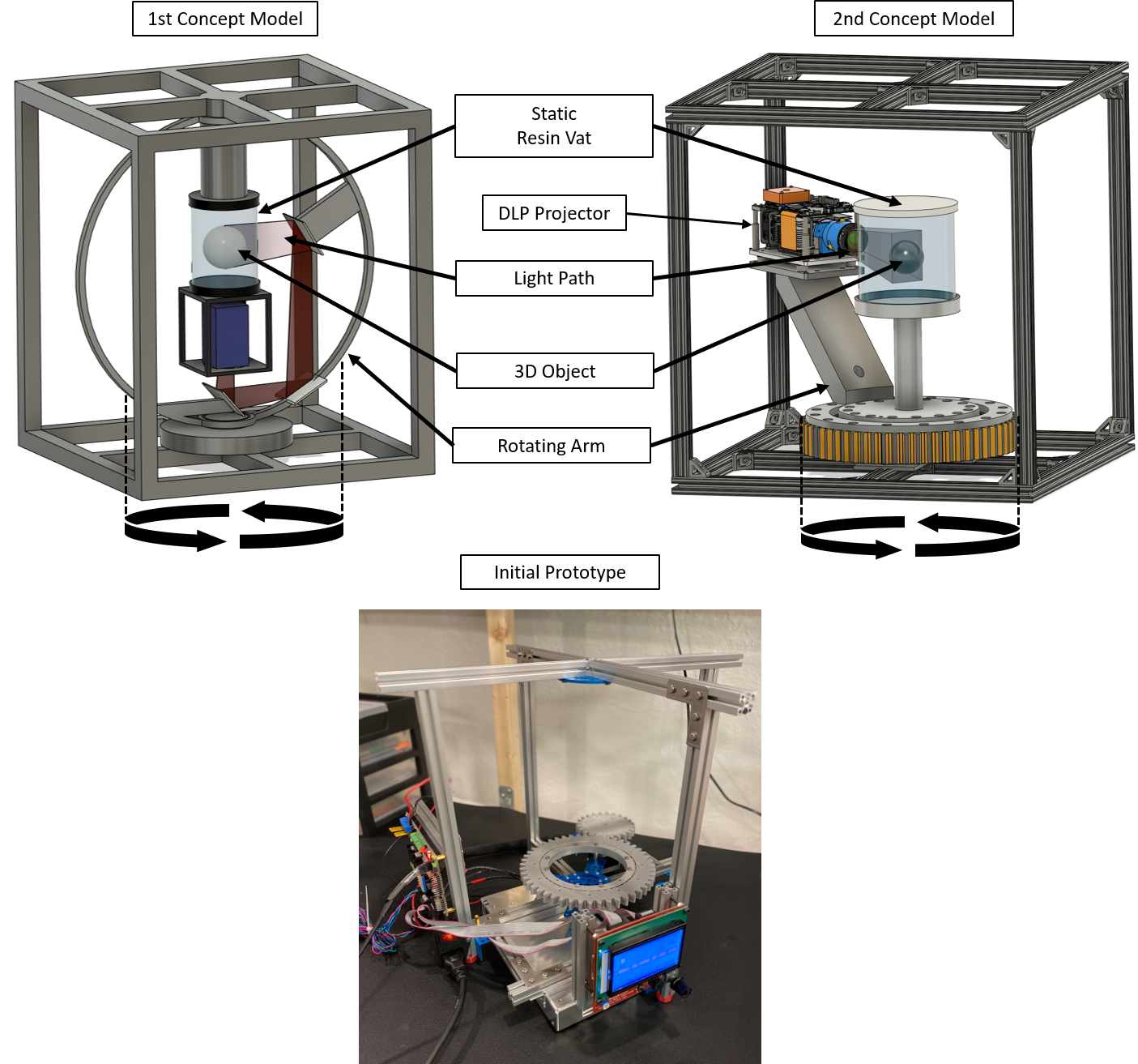
As seen in my previous blog post, below are images of the first and second concept models, along with images of an initial prototype.

The initial prototype seen above worked well and was capable of simple rotating motion using an LCD controller and a Rumba controller board running traditional Fused Deposition Modeling (FDM) 3D printer firmware (Marlin). The frame was constructed from 15x15mm aluminum extrusion; however, not enough material was available to create the boxed frame seen in the 2nd concept model.
Previous Limitations: System Interface and Frame
While testing the motion capabilities of the first prototype three limitations became painfully obvious. The first limitation was that the firmware configuration on the controller board was not easily modifiable. For each setting change, such as rotational speed, the firmware had to be modified in a script editor such as Arduino Integrated Development Environment (IDE). Then the controller board had to be reflashed with the updated firmware. Secondly, the menu system on the LCD interface control was clunky and often misselected menu options. I knew that prototyping during the testing and optimization phase would take much longer if I didn’t make the controller parameters easier to change with a more intuitive menu interface. Lastly, the frame, slew bearing, and armature were not properly balanced which became obvious during multiple bearing rotations.
Applying Solutions: Controller Board & Frame Upgrades
Controller Board Upgrade
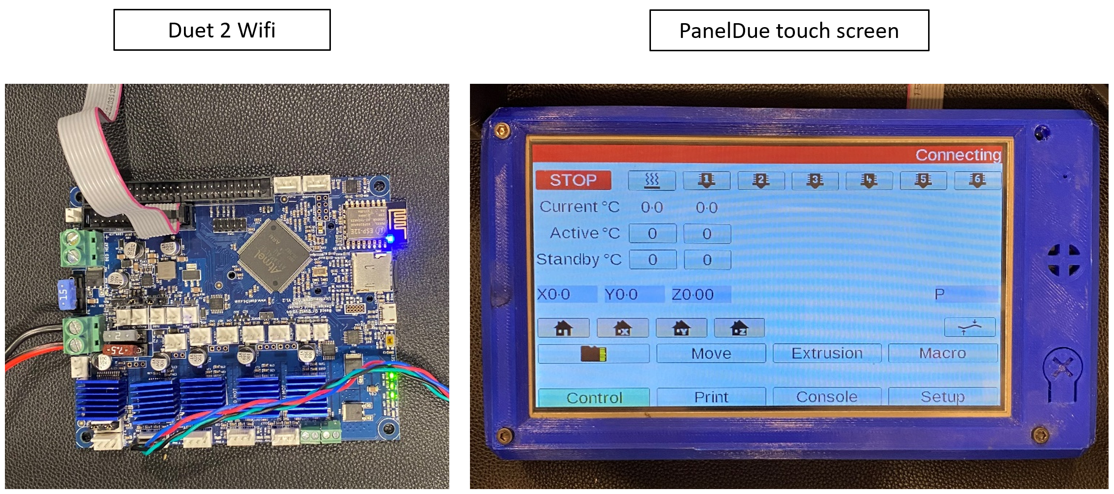
The first solution was to upgrade the controller board to the Duet 2, an internet-enabled system that allows the user to quickly make changes on a web interface connected to a local wifi network. This system is also compatible with a touch screen interface called PanelDue that provides easy touch capability and essential system information.

The Duet systems provides a 32bit processor and increased resolution of the stepper motor drivers. The web interface allows for easy modifications of settings without reflashing the firmware. The user can also store macros for motions that are often used. It is also possible to couple the Duet with other microcontrollers or computers, which will be needed once a DLP projector is attached. The second solution integrated a touch screen interface which allowed for direct control of the controller board and motion system.
Frame Upgrade
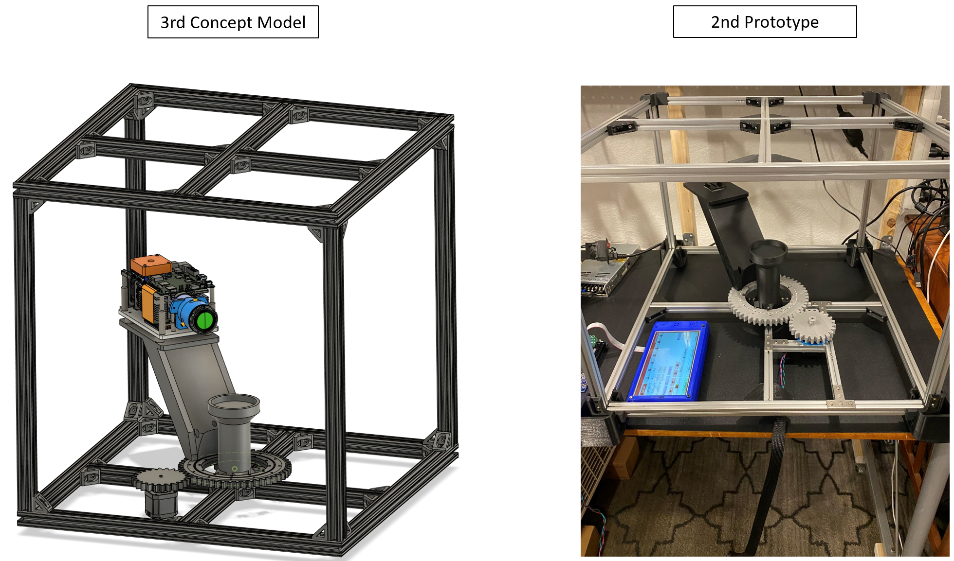
The final solution consisted of assembling a sturdy boxed frame as depicted in the 2nd concept model above. Long pieces of 15×15 aluminum extrusion were ordered and cut to size. Having never cut aluminum before, I found out that small sharp pieces fly everywhere, so wear your safety goggles and gloves. Next, 3-way corner brackets and wedge brackets were used to attach aluminum pieces in a box-cross formation. Once the frame was complete, an additional aluminum piece was added to connect the stepper motor in place.

Bearing and Armature Upgrade
Once the frame was assembled, it was time to attach the previously shown 3D printed slew bearing, which can be seen again below. The cylinder-shaped 3D printed bearings were initially printed using PETG filament. However, this leads to significant noise and rugged movement. The bearings were printed at higher resolution using low friction polymer filament to solve these issues, leading to decreased noise and smoother motion. It may even be useful to print the gear assemblies out of the same material to further reduce these issues.

Before the slew bearing could be connected, a bearing mount was 3D modeled, printed, and attached to the frame. This mount also contained a vertical “cup” platform designed to hold a cylindrical container of photocurable resin. Once the slew bearing was mounted, the DLP armature platform was next. The armature base was modeled to fit on the outer ring closest to the spurs using only three bolts. After attaching the armature, a GoPro mount was fixed to the platform. This will be used to obtain the view of the DLP projection until one can be purchased.
Prototype Motion and Observations
The video on the left demonstrates the motion path the projector will take represented by the mounted GoPro. The video on the right shows the DLP projection target (the resin vat) represented by a glass of water. This current prototype seen in the video is far from complete and there are several pitfalls that I have noticed during the test operation.
First, the armature has too much flexibility even with every little weight applied. This is due to the extremely sparse infill used when fabricating the part. It was the largest single print part that I have ever made and took 34 hours to complete. Increasing the infill and increasing the gear’s surface area to the armature interface will help reduce flex. However, careful consideration must be made to avoid unnecessary increases in armature weight, especially with a mounted projector.
Secondly, there is still noise and rugged motion being seen between the smaller and larger gears. Fabricating the gears entirely out of the Igus filament could be a possible solution. Changing the gear configuration to a herringbone design and changing the ratio may provide smoother operation while increasing available torque.
Next Steps: Smoothing the Motion System
The next steps involve testing the system using vibration sensors attached to multiple areas: the slew bearing and the armature. The goal will be to obtain an idea of where the most vibration occurs and then make design changes to minimize those occurrences.
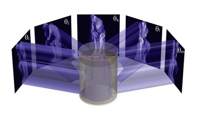
Finally, getting a development module DLP projector would be the step that helps propel this dream into a reality. If a projector was procured, configuring and testing complex light projections on the photocurable resin in sequence with rotation would help to tune in the parameters necessary to obtain a viable volumetric 3D print.
I look forward to continuing the testing and optimization process and dream of the day that I can attach a DLP projector and begin to 3D print volumetrically! This project has taught me that parametric 3D modeling using manufacturer CAD models combined with user-designed components can make the fabrication process much more efficient. Materials can be inserted, adjusted, and tested before purchasing. Also, motion studies can be performed, removing possible errors that could cause frustration and timely setbacks.
I will continue developing this project, and I encourage all those interested to contact me as feedback is always appreciated. I would like to thank Loretta C. Duckworth Scholars Studio (LCDSS) staff for allowing me to explore this exciting concept. Their support and suggestions were incredibly helpful, and I could not have done this without them.
