This project captures the excitement of the NASA Mars Rover mission. Using an old 27 MHz R/C car as a base, the 2004 ECE undergraduate capstone design team stripped away everything except the DC drive and steering motors and the chassis. A large plastic enclosure is the new body.
The embedded computer is a LogicFlex 25 MHz, 32-bit i386EX microcomputer (JK Microsystems,www.jkmicro.com), which has 46 digital input/output (I/O) lines and two RS232C serial ports. Since the on-board sensor suite chosen primarily provides analog signals, the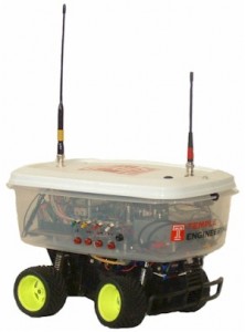 LogicFlex is mated to its Multi-I/O peripheral board, which has 8 12-bit analog-to-digital converter (ADC) channels, 4 12-bit digital-to-analog converters (DAC), and 8 optoisolated high current driver ports. The LogicFlex uses DOS and is programmed in C, C++, and assembly language using the Borland V4.52 development environment.
A variety of real-world sensors are integrated into the Rover. A biaxial tilt sensor (model 0729, Fredericks,www.frederickscom.com) provides analog pitch and roll signals. Since the Rover will be going up and down inclines, a tilt compensated electronic compass (model TCM2, PNI, www.pnicorp.com) with a triaxial magnetometer is used to measure the true magnetic vector as an analog signal. A triaxial, solid-state transducer (model CXL04LP3-R, Crossbow, www.xbow.com) outputs 3 analog signals proportional to acceleration. This sensor suite uses 6 of the 8 available ADC channels.
The two remaining ADC channels are used to provide feedback on the position of the steering axle of the Rover with a potentiometer and to monitor the main battery voltage. Finally, a GPS receiver (model 25, Garmin, www.garmin.com), that outputs an RS232C serial ASCII data string reporting satellite acquisition and a valid position, is interfaced to one of the LogicFlex UARTs.
Both the Rover and the Base Station require a data modem. Two 1200 bps AFSK half duplex modems are built using the MX-COM MX614 IC. The data terminal ready (DTR) line of the RS232C serial interface controls the transmit or receive mode of the modem and transceiver. A Maxim MAX232 IC provides TTL to RS232C voltage level conversion.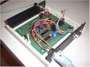
The Rover 144 MHz HT data transceiver is a Kenwood TH-25AT. Operating the HT on 12 VDC produces an output of either 0.4 W on low or 4.2 W on high power. The high/low switch was interfaced to an optoisolated driver port of the LogicFlex for RF power control. The Base Station 144 MHz data transceiver is a Kenwood TM-721A. The Based Station 2 meter antenna is normally a 3 element Yagi, which shares the boom with a 7 element Yagi for receive-only ATV (model 146/437-10WBP, Arrow Antennas,www.arrowantennas.com).
 A 2 meter simplex frequency, typically 146.58 MHz, is used for data communication. A shortened 2 meter antenna (rubber duckie) is mounted at one end of the lid of the plastic body. An aluminum plate under the lid provides a reasonable ground plane for the Rover antennas.
Since you have to see where you are driving the Rover, a 1 W 426.25 MHz ATV transmitter with a 4.5 MHz audio subcarrier modulator and solid-state color camera with microphone are on the Rover and an ATV downconverter is at the Base Station (models TXA5-RCb, FMA5, LB1000, and TVC-4G, P C Electronics, www.hamtv.com). A shortened 70 cm antenna is mounted at the other end of the Rover lid.
Although AX.25 could have been used for the Rover, a custom client-server protocol is developed as part of the capstone design experience. Only the Base Station c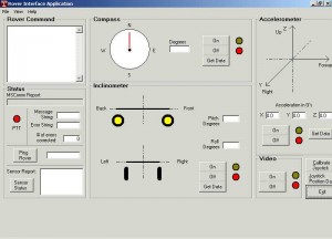 lient can initiate digital data communication with the Rover server. The client protocol, the Rover Interface Application (RIA), is written in Visual Basic and executes on a PC at theBase Station. The RIA displays sensor data in both numerical and graphical form. Graphics require more programming but produce visually meaningful displays. The server protocol, the Rover Operation Application (ROA), is written in C and assembly language and executes on the LogicFlex on the Rover
RIA commands consist of a single 7-bit ASCII character. An ROA response is either an echo of the RIA command or an echo with appended ASCII numerical characters for the requested sensor data. Commands allow the Rover sensors and the ATV subsystem to be turned on and off to conserve b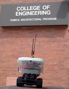 attery power and to control the forward and reverse speed of the drive and the position of the steering motor in discrete increments.
Each 7-bit ASCII character is encoded as an 11-bit message using an error correction code (11,7 Hamming block code). In what might seem like magic, this code can sense and correct a single bit transmitted in error. A synchronization, or sync, header is appended to the beginning to form a message that is a multiple of 8-bits long. The sync header is used to alert the Rover that a message is incoming, since the data receiver squelch is turned off.
The Rover DC drive and steering motors are controlled by pulse width modulation (PWM), with the on-off timing of PWM set by a software interrupt routine and a real-time clock on the LogicFlex. The Rover is a semi-autonomous vehicle and will shut down if data communication with the Base Station is corrupted or lost. The pitch and roll transducers can abort the Rover’s movement if trouble is sensed. Of course, the Rover also sends the K3TU club call sign every ten minutes for identification and has a watchdog timer in software for the data tran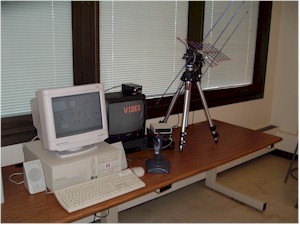 smitter.
The Base Station RIA initiates all communication with the Rover. A joystick on the PC is used to send drive and steering commands, but can be overridden in a panic with the keyboard. Using the K3TU club station antennas on 146.58 and 426.25 MHz, Yagi antennas at 150 feet, the Rover has been controlled and the surroundings seen and heard at a distance of over 5 miles.
The Rover capstone Senior Design project was by a team of ECE undergraduates: Steve Herman, John Dessino and John Falcone, KB3KDM. The Rover final report is available (roverfinalreport).