Address Locating Trees in Philadelphia Neighborhoods

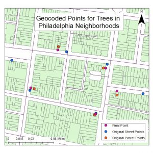
This final PHS project sought to create an address locator that would move points from the center of a parcel to just outside it. These points were to represent neighborhood trees. The process was completed and managed using address locator tools in ArcMap. Please refer to the image at the end for reference to the project results.

  1. First navigate in ArcToolbox to the following tool: Geocoding Tools/Create Address Locator
  2. Input the following information and create the geocoders:
    1. Parcels:
      1. Address Locator Style: General- Single Field
      2. Reference Data: City of Philadelphia PWD Parcels
      3. Key Field: ADDRESS
      4. Name: Parcels
    2. Streets:
      1. Address Locator Style: US- Dual Ranges
      2. Reference Data: Philadelphia Street Centerline
      3. Key Fields will fill in automatically
      4. Name: Streets
  3. Editing the Street Geocoder for Accuracy:
    1. Once the Street geocoder is created right click on the tool in ArcCatalog
    2. Navigate to the properties
    3. Open the ‘Geocoding Options window
    4. Set ‘Side Offest’ to 25 feet.
    5. Apply changes and close the window
  4. Navigate to the following tool: Geocoding Tools/Geocode Addresses
  5. Input the following information to create geocoded points for trees using parcels:
    1. Input Table: Trees
    2. Input Address Locator: Parcels
    3. Input Address Fields: Key Field: ADDRESS
    4. Name: Trees_parcels
  6. Navigate to the following tool: Geocoding Tools/Reverse Geocode
  7. Input the following information to create final points using the street geocoder:
    1. Input Features: Trees_parcels
    2. Input Address Locator: Streets
    3. Output Feature Class: Final_trees

Developing Routes for Groups of Land Maintenance Sites

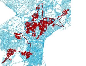
Over the past eight weeks, I have been working for PHS for my capstone project. As many may have seen my updates on this site. The project has pretty much come to an end and been troubleshot! Because of this, I have taken on a few additional projects that I will post about. This project, sought to find an easy way to create a route that we could give to contractors instead of just a bunch of addresses that they would have to sort through themselves. In an effort to do this, I utilized Network Analyst in ArcMap as the team is familiar with the tools and their functionality. Below, I have included the step by step guide that I gave to the team for the future as well as a few pictures of the outcome!

Each route will be designated by pre-defined groups of sites if they exist for the data that is being managed. This tutorial will use the Maintenance Only (MO) Reentry Site Shapefile as an example.

  1. Navigate to and add the following shapefiles to ArcMap:
    1. “U:\PhiladelphiaLandCare2\06_AllCurrentYearWork\2017\Shapefiles\MO_Reentry_parcels2017_ACYW.shp”
    2. “U:\02_External_data\Streets\Phila\Phila_Street_Centerline_ND.nd”
  1. Enable the ‘Network Analyst’ toolbar under the Customization tab on the top left of ArcMap. You may need to go to the extensions tab, also under Customization and enable Network Analyst as well. This is only necessary if you have never used Network Analyst before.
  2. Once we have enabled the toolbar, it should pop-up in the middle of the ArcMap window. This is okay, but feel free to move it if you are bothered. Look around the tool and get a feel for the set-up. Be sure to enable the ‘Network Analyst Window’ as we will take advantage of this in later steps. This is the first icon from the left.
  3. Next, using the dropdown menu in Network Analyst, select ‘New Route’. This will add a series of empty layers to both the Analyst Window and the Table of Contents.
  4. We will next add the points or ‘Stops’ as the route generator calls them to the Analyst Window. Before we can do this, we will need centroids of our sites we are routing.
    1. To begin, navigate to the attribute table of the MO parcels shapefile. Add two fields with the following names with the field type as ‘double’: x_coord and y_coord.
    2. Next, right click on the name of the field in the attribute table. Navigate to ‘Calculate Geometry’. Click next until you get to the main window. Here set the geometry we are calculating to the respective centroid field (x_coord calculates ‘X Coordinate of Centroid’). Repeat this with the other coordinate.
    3. Export the attribute table as a ‘.dbf’ to your workspace. Add the table to the map image.
    4. Right click on the table in the table of contents. Navigate to ‘Display XY Data’. Here, set X = x_coord and Y = y_coord. Click okay. You should now see centroids for all the MO sites in Philadelphia County.
    5. Export the table to your working folder and add the shapefile to the map. This will be our centroid shapefile for the remainder of the assignment.
  5. Next, we will add the centroids to Network Analyst as ‘Stops’. To do this, right click on ‘Stops’ in the Network Analyst Window on the far left of your screen. Navigate to ‘Load Locations’. Set the ‘Sort Field’ and ‘RouteName’ to the grouping factor. For many shapefiles, this will be ‘Group’ or ‘Group_Number’. In this shapefile, the grouping factor is ‘Contractor’. Leave all other factors as they are. Once this is done, click okay. The loading may take a moment.
  6. Now we will make the routes. To do this, go back to the Network Analyst Toolbar and click on the small button labeled ‘Solve Network’. Be patient as this may take a bit of time again.
  7. A series of routes should now be visible for reach of the contractors or groups that we based our breaks on or ‘Sort Field’. To see where the stops are along the routes, select the ‘Network Directions’ button, again on the Toolbar. Each route will be displayed with the stops along the routes and the address of each site. Export this table as you see fit, as these are your results. Be patient working through this as there are many sites run through each time.
    1. Note: It may work to partition the sites into smaller shapefiles before the Solve is run. This would occur via a ‘Select by Attribute’ for the group or groups in question, then perform steps 6 – 8 for each individual group. This would be tedious to select each group, but could speed up processing slightly without coding the process externally.
  8. Each route can be exported individually by right clicking it in the Network Analyst Window and selecting export. If the entire shapefile is exported at once, each route will be combined into one. This could be broken down using the geoprocessing ‘Dissolve’ function if you would like to streamline with only two steps.


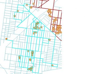
Below, the first image is of all routes created using the Philadelphia County Streets Network. The second image shows one route zoomed in with the sites that are navigated to.


Testing and Troubleshooting PHS LandCare Update Process

During this sprint of my capstone project, I worked on doing a final run-through of the process I had written for PHS’ LandCare updates and updated the documentation. Over the course of the project I had run each section individually, but had not run all together. Because I had failed to review the way in which many of the shapefiles interact with each other in further sections, I had not considered that some changes may affect other processes.

With my update test, I found that a number of the geometry functions could not work when tested all together. Some functions that failed include: copying or inserting geometries, exporting and updating geometries. Because of this, the first major issue to handle was the type of geometry the project intended to use. Originally, each shapefile had been imported with ArcMap ST geometry, a form that would not be compatible for export from SpatiaLite. Eventually after some level of significant research, I found that the SpatiaLite geometry with the SRID specified in the PHS selected projection (2272, Pennsylvania State Plane South) would work for this project. Eventually I worked out with some troubleshooting that an R-Tree Index could not be specified upon upload for further updates in QGIS.

Next, I found that without the ST geometry format, it would not be possible to use the ST_Union function that was relied upon heavily in the update process. This was remedied using QGIS. Once corrected, it would be possible to connect to the database in QGIS then utilize a plugin called ‘Geometry Updater’. This plugin allowed for us to manipulate geometries when moved from one table to another (like every single one of our update procedures). Once run, geometries were updated in the shapefiles based on the field specified using a reference shapefile.

Finally, when exporting, I found that the ‘CREATE TABLE AS’ option would not function with the changed geometry type. Because of our need to manipulate columns and change their names for the City of Philadelphia data management system, we needed a new way to export. Again, a QGIS plugin was used to change column names, delete columns, and reorganize them in the shapefile. The completed shapefile can then be exported and opened in ArcMap where the ArcMap specific metadata can be added. Because of the unique ESRI format, it was not possible to streamline this through SpatiaLite or QGIS.

When all is said and done, the final product takes about 30 minutes to run. This does not include the download of software and major excel preparation. As our new data changes come from one large audit excel, it is important to make sure we adjust the data for what we want before copying to the metacoding spreadsheets. An example of this could be the address updates and their ambiguity. Because some address updates will read as “Update address to 1501 – 1507 N 15TH ST” we will have to pick through and determine what needs to be added. While this can still take some time, the overall method is much faster than what was performed previously in ArcMap.

Using Remote Sensing to Show Land Changes with Highway Construction

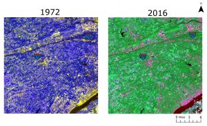
This past semester, through my remote sensing course, I had the opportunity to analyze land changes that result from the construction of highways. Specifically images from 1972 and 2016 of route 476 were analyzed using remote sensing software. The land analyzed was tested for changes in urban spaces, grass, forest, and water. These for areas allowed for the best analysis with the most understandable results. The original composite images (bands 4, 5 and 7) are shown below prior to any testing or remote sensing analysis.

Highway 467 was the primary area of interest for this analysis as the construction in the Philadelphia area was regarded as highly controversial. Construction of the highway took many years, and removed many homes, trees, and other green space. This analysis sought results showing the amount of green space removed for construction purposes. This area would have been replaced with urban space.

Results were calculated using some ArcMap analysis but primarily ENVI software was used. All final maps were edited for readability and clarity using Adobe Illustrator. The following analysis was performed: a tasseled cap analysis, a supervised land classification using a majority analysis, and land change results were calculated.

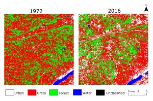
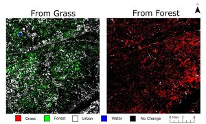
Shown below, the classification shows the land in the original state (1972) and the final state (2016). It is evident when viewing this map, that there was some change in land type from grass or forest to urban spaces. While much of this was due to highway construction, it could be interpreted that the highway led to the urbanization of the surrounding suburbs.

The image below is a deeper explanation of the land that changed from forest or grass to the new land it consists of. What seemed interesting with these results were that much of the forest land changed to urban but also grass land. This was also similar with grass land and vice versa. One consideration for this could have been the increased interest in large green backyards. While many new homes were constructed, these homes typically had large sprawling yards. The area analyzed is primarily upper class when median household incomes were considered in this analysis.

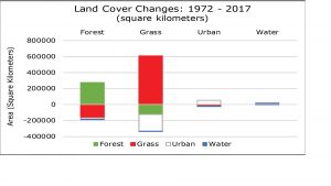
Finally, the image below depicts the actual land changes from one category to another when analyzed in square kilometers. As was unexpected, much of the forest and grass land changed from one to the other. Yes, urban space was gained significantly, but the amount of grass and forest retained was entirely unexpected.  Future analysis should consider the type of forest growth (primary, secondary, etc) to determine the overall growth and health of the newly greened land spaces.

The overall results of this project showed that much greenspace was lost to urbanization with the construction of highways, but much land was retained and converted to other types of greenspaces. Future analysis suggests that a consideration of these new greenspaces be tested. While greenery is implemented, the overall health of the area has not been considered. As many plain greenspaces can harm environmental health, forest density versus grass should be regarded as an important future testing point.

Updating Addresses and Adding New LandCare Sites for PHS

During sprint two of my capstone with PHS, I worked on finishing the update structure for LandCare Project shapefiles. As we were updating both parcels and sites, code was required for each subset of data. To streamline the process, I used metacoding like what was posted in my first blog post. There were two main processes that were coded in this sprint: address updates and the addition of whole new sites. Both will be discussed in this blog post.

I have found it best when explaining the parts of this project to think about parcels and sites as Lego bricks and structures respectively. Consider an individual Lego brick. Singularly it does a job and has a function, just as a land parcel does as a singular address. But, when parcels are added together they become sites that consist of multiple addresses. This could be considered to when several Lego bricks are combined to make a structure. There is still the ability to remove or add bricks but the overall geometry of the structure will change.

This is comparable to the address addition and removal process. As we add a new parcel or brick, we must also update the sites file as the geometry is changing. This is also true for the removal of a parcel. While the changes we are making may include only the addition of one small parcel or brick, the site geometry or structure changes significantly. This requires a special geometry update in SQL to ensure that these changes are not missed accidentally in a shapefile update.

These address updates were broken into two separate metacoding files: address addition and address removal. Address addition utilized data for parcels from the Philadelphia Water Department to provide geometries for new parcels being added to sites. Each parcel was individually added to the parcels file first with the selection of the geometry and other unique fields from the PWD parcel data. Following, data was updated for the parcel file for the new address range. Other parcel information was copied from other parcels in the site we were interested in. The code for these parts has been pasted below.

INSERT INTO PLCmaint_parcels_2017 (ADDRESS, Geometry)
SELECT ADDRESS, Shape
FROM allparcels_517
WHERE ADDRESS = "1501 N 15TH ST";

UPDATE PLCmaint_parcels_2017
SET PARCELID = (SELECT PLCmaint_parcels_2017.PARCELID FROM PLCmaint_parcels_2017 WHERE PLCmaint_parcels_2017.ADDRESS = "1503 N 15TH ST"),
    TENCODE = (SELECT PLCmaint_parcels_2017.TENCODE FROM PLCmaint_parcels_2017 WHERE PLCmaint_parcels_2017.ADDRESS = "1503 N 15TH ST"),
    OWNER1 = (SELECT PLCmaint_parcels_2017.OWNER1 FROM PLCmaint_parcels_2017 WHERE PLCmaint_parcels_2017.ADDRESS = "1503 N 15TH ST"), 
    OWNER2 = (SELECT PLCmaint_parcels_2017.OWNER2 FROM PLCmaint_parcels_2017 WHERE PLCmaint_parcels_2017.ADDRESS = "1503 N 15TH ST"),
    BLDG_CODE = (SELECT PLCmaint_parcels_2017.BLDG_CODE FROM PLCmaint_parcels_2017 WHERE PLCmaint_parcels_2017.ADDRESS = "1503 N 15TH ST"),
    BLDG_DESC = (SELECT PLCmaint_parcels_2017.BLDG_DESC FROM PLCmaint_parcels_2017 WHERE PLCmaint_parcels_2017.ADDRESS = "1503 N 15TH ST"),
    BRT_ID = (SELECT PLCmaint_parcels_2017.BRT_ID FROM PLCmaint_parcels_2017 WHERE PLCmaint_parcels_2017.ADDRESS = "1503 N 15TH ST"),
    GROSS_AREA = (SELECT PLCmaint_parcels_2017.GROSS_AREA FROM PLCmaint_parcels_2017 WHERE PLCmaint_parcels_2017.ADDRESS = "1503 N 15TH ST"),
    Shape_Area = (SELECT PLCmaint_parcels_2017.Shape_Area FROM PLCmaint_parcels_2017 WHERE PLCmaint_parcels_2017.ADDRESS = "1503 N 15TH ST"),
    PID = (SELECT PLCmaint_parcels_2017.PID FROM PLCmaint_parcels_2017 WHERE PLCmaint_parcels_2017.ADDRESS = "1503 N 15TH ST"),
    Year = (SELECT PLCmaint_parcels_2017.Year FROM PLCmaint_parcels_2017 WHERE PLCmaint_parcels_2017.ADDRESS = "1503 N 15TH ST"),
    Season = (SELECT PLCmaint_parcels_2017.Season FROM PLCmaint_parcels_2017 WHERE PLCmaint_parcels_2017.ADDRESS = "1503 N 15TH ST"),
    VL_Num = (SELECT PLCmaint_parcels_2017.VL_Num FROM PLCmaint_parcels_2017 WHERE PLCmaint_parcels_2017.ADDRESS = "1503 N 15TH ST"),
    Sq_Ft = (SELECT PLCmaint_parcels_2017.Sq_Ft FROM PLCmaint_parcels_2017 WHERE PLCmaint_parcels_2017.ADDRESS = "1503 N 15TH ST"),
    Trees_Num = (SELECT PLCmaint_parcels_2017.Trees_Num FROM PLCmaint_parcels_2017 WHERE PLCmaint_parcels_2017.ADDRESS = "1503 N 15TH ST"),
    TARGETAREA = (SELECT PLCmaint_parcels_2017.TARGETAREA FROM PLCmaint_parcels_2017 WHERE PLCmaint_parcels_2017.ADDRESS = "1503 N 15TH ST"),
    Grid = (SELECT PLCmaint_parcels_2017.Grid FROM PLCmaint_parcels_2017 WHERE PLCmaint_parcels_2017.ADDRESS = "1503 N 15TH ST"),
    CCD = (SELECT PLCmaint_parcels_2017.CCD FROM PLCmaint_parcels_2017 WHERE PLCmaint_parcels_2017.ADDRESS = "1503 N 15TH ST"),
    ZIPCODE = (SELECT PLCmaint_parcels_2017.ZIPCODE FROM PLCmaint_parcels_2017 WHERE PLCmaint_parcels_2017.ADDRESS = "1503 N 15TH ST"),
    Action = (SELECT PLCmaint_parcels_2017.Action FROM PLCmaint_parcels_2017 WHERE PLCmaint_parcels_2017.ADDRESS = "1503 N 15TH ST"),
    TARG_GRID = (SELECT PLCmaint_parcels_2017.TARG_GRID FROM PLCmaint_parcels_2017 WHERE PLCmaint_parcels_2017.ADDRESS = "1503 N 15TH ST"),
    CCD_Person = (SELECT PLCmaint_parcels_2017.CCD_Person FROM PLCmaint_parcels_2017 WHERE PLCmaint_parcels_2017.ADDRESS = "1503 N 15TH ST"),
    Program = (SELECT PLCmaint_parcels_2017.Program FROM PLCmaint_parcels_2017 WHERE PLCmaint_parcels_2017.ADDRESS = "1503 N 15TH ST") 
WHERE ADDRESS IN (
                SELECT ADDRESS
                FROM PLCmaint_parcels_2017
                WHERE PLCmaint_parcels_2017.ADDRESS = "1501 N 15TH ST");

UPDATE PLCmaint_parcels_2017
SET NumParcels = "13",
    Addr_Range = "1501 - 1507 N 15TH ST"
WHERE VL_Num = "VL0123EN_CLP";

Once parcel information was added and correct, the site shapefile geometry was updated accordingly. This was the product of a ST_Union function that inserted new geometries into the sites table in SpatiaLite. Address ranges and parcel numbers were updated accordingly as shown in the code block below.

UPDATE PLCmaint_SITES_2017
SET Geometry = (
                SELECT ST_Union(Geomtery)
                FROM PLCmaint_parcels_2017
                GROUP BY VL_Num);

UPDATE PLCmaint_SITES_2017
SET NumParcels = "13",
    Addr_Range = "1501 - 1507 N 15TH ST"
WHERE VL_Num = "VL0123EN_CLP";

Parcel removal required the copy of parcel data first to the New Use table so changes would be documented for the future. Once this was done, the parcel was deleted from the parcel table. The site geometry was updated following the same process as previously. Address ranges and parcel numbers were updated accordingly. This code can be visualized below for reference.

INSERT INTO NewUse_2017 (PARCELID, TENCODE, ADDRESS, OWNER1, OWNER2, BLDG_CODE, BLDG_DESC, BRT_ID, GROSS_AREA,
    Shape_Area,VL_Num, Sq_Ft, Trees_Num, PID, TARGETAREA, Grid, CCD, Addr_Range, ZIPCODE, Geometry)
SELECT PARCELID, TENCODE, ADDRESS, OWNER1, OWNER2, BLDG_CODE, BLDG_DESC, BRT_ID, GROSS_AREA, Shape_Area, VL_Num, 
    Sq_Ft, Trees_Num, PID, TARGETAREA, GRID, CCD, Addr_Range, ZIPCODE, Geometry
FROM PLCmaint_parcels_2017
WHERE ADDRESS = "1501 N 15TH ST";

DELETE FROM PLCmaint_parcels_2017
WHERE ADDRESS = "1501 N 15TH ST";

UPDATE PLCmaint_parcels_2017
SET NumParcels = "12",
    Addr_Range = "1503-1507 N 15TH ST"
WHERE VL_Num = "VL0123EN_CLP";

UPDATE PLCmaint_SITES_2017
SET Geometry = (
                SELECT ST_Union(Geometry)
                FROM PLCmaint_parcels_2017
                GROUP BY VL_Num);

UPDATE PLCmaint_SITES_2017
SET NumParcels = "12",
    Addr_Range = "1503-1507 N 15TH ST"
WHERE VL_Num = "VL0123EN_CLP";

Adding new sites entirely was a straightforward process. Four sections of metacoding were used to break down information and explain steps. The data was copied from provided shapefiles into the parcels table first, then the sites.

For the sites table update, the VL numbers (unique parcel identifier) were selected with a “SELECT DISTINCT” statement and these were copied into part three. This allowed for only the information for one parcel to be copied into the sites table, representing the data for the site that was available. Finally the site geometry was updated using the ST_Union feature described above. The code used is visible below.

INSERT INTO PLCmaint_parcels_2017 (PARCELID, TENCODE, ADDRESS, OWNER1, OWNER2, BLDG_CODE, BLDG_DESC, BRT_ID, 
    GROSS_AREA, Shape_Area, Year, Season, VL_Num, NumParcels, Sq_Ft, Trees_Num, TARGETAREA, Addr_Range, Geometry)
SELECT PARCELID, TENCODE, ADDRESS, OWNER1, OWNER2, BLDG_CODE, BLDG_DESC, BRT_ID, GROSS_AREA,Shape_Area, Year, 
    Season, VL_Num, NumParcels, Sq_Ft, Trees_Num, TARGETAREA, Addr_Range, Geometry)
FROM Fall16_Stabilization_parcels;

SELECT DISTINCT VL_Num
FROM Fall16_Stabilization_parcels;

INSERT INTO PLCmaint_SITES_2017 (VL_Num, ADDRESS, Year, Season, NumParcels,  Sq_Ft, Trees_Num, TARGETAREA, Addr_Range, Geometry)
SELECT VL_Num, ADDRESS, Year, Season, NumParcels,  Sq_Ft, Trees_Num, TARGETAREA, Addr_Range, Geometry
FROM Fall16_Stabilization_parcelsGROUP BY VL_Num HAVING VL_Num = "VL0123EN_CLP";

UPDATE PLCmaint_SITES_2017
SET Geometry = (
                SELECT ST_Union(Geometry)
                FROM PLCmaint_parcels_2017
                GROUP BY VL_Num);

Any resulting data from these sections were queried to double check the work. My sprint three blog will cover the exporting of these tables to shapefiles and will use visualizations.
Using Metacoding for Philadelphia LandCare Site Manipulation

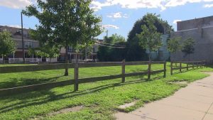
For my capstone project, I will be working with Pennsylvania Horticulture Society to develop a streamlined data management system for their LandCare Program. The LandCare Program strives to rehabilitate vacant land parcels in the city of Philadelphia to address urban revitalization and land vacancy issues plaguing the city. The image below shows what some of these land areas can look like.

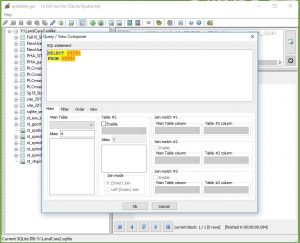
The project has so far consisted of the construction of a database in SpatiaLite to work with the shapefiles for the project, see the image below for an overview of the GUI. I selected SpatiaLite as it uses the SQLite language and connects seamlessly with ArcMap. This ultimately allows the user to create an manipulate geodatabases using code written in SpatiaLite and immediately access the results in ArcMap.

My first sprint (May 30th to June 8th) consisted primarily in the set up of documentation for the project, in addition to the following items: creating a geodatabase, working to remove sites that have new uses (no longer PHS LandCare sites) as well as writing base code for updating tables based on an excel.

The process to create documentation was decided upon so formal directions would be available for anyone working on this project in the future. In addition to this, I have detailed notes of what I have done thus far and can change information as the project progresses.

Most of the coding that has been done thus far has been metacoded in excel. By doing this, the overall update process is now streamlined to where someone with no SQL experience can use the excel and get valid results. Using the image below, an example to delete a row from a table in SpatiaLite, it is visible that the user only must input a small amount of information such as the table name and the identifier for the row being deleted. This will benefit not only the inexperienced coder in the future, but also anyone who must update many files at once as only one column must be manipulated. The end result will be to gain statements that can be copied and pasted in the query window of SpatiaLite.

So far, there are metacoding files for updating new use sites and updating columns overall. When updating new use sites, we must copy information from both parcels (individual lots) and sites (many lots together) to develop one overarching row of data. This process was broken down into four steps, two with updates and two for deleting the land area from the new parcel and site tables as they are no longer in the maintenance database. The individual update metacoding was created for a quick update like square feet. Using this process, much information can be quickly added to the pre-written code and then executed in SpatiaLite.

Finally, in sprint two, the next process will be determining the process to update parcel and site data for address changes. As many sites may lose a parcel or gain a parcel over the course of the year for maintenance purposes, it is important that adequate files are maintained on current geometries. This will most likely be completed again with many steps in the form of a metacoded file.