Atomic Force Microscopy
The Strongin research group has two scanning probe microscopes an Agilent 5100 (formerly Molecular Imaging Pico LE) and a Veeco Multimode. The Agilent instrument is a tip scan instrument, equipped with small (10 µm) and large AFM scanners (150 µm), as well as a 2 µm STM scan head. This instrument is equipped with an environmental chamber, is capable of heating to 200 C, and is excellent for working in solution. The Veeco Multimode is a sample scan instrument with a large area scanner. Tip scan and sample scan refer to the location of the piezo in the instrument’s design, the part of the system that actually moves during data collection.
AFM Basics
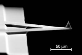
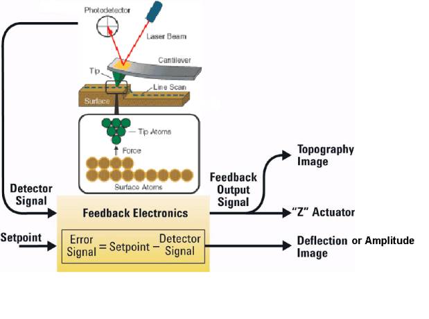
Atomic Force Microscopy (AFM) is a type of scanning probe microscopy (SPM) where a sharp probe R<10 nm (figure 1) interacts with the sample surface to reveal physical properties. Scanning tunneling microscopy (STM) is another common form of SPM. SPM techniques operate by using a feedback loop. In a feedback loop some criteria is set, and the instrument continually adjusts in an attempt to maintain the set point of that parameter. Typical feedback loop parameters are tip deflection or amplitude for AFM, and current or height for STM. In an AFM, a laser is aligned on the backside of the cantilever (probe) and reflected into a four quadrant photodiode. As the probe moves across the sample surface, an image is created on a computer screen pixel by pixel based on the signals obtained from the photodiode and the feedback loop.
There are two primary modes of AFM operation, contact and intermittent contact. Almost all AFM image types can be related back to these two modes, as they are simply the result of different methods of tip excitation or the collection of alternate signals.
In contact mode AFM, the tip is pushed into the sample surface resulting in some amount of deflection measurable in the photodiode. The amount of force exerted on the sample surface is a function of the tips spring constant (force constant) and the amount of deflection (how much the tip has been bent), essentially Hook’s law. While working in contact mode deflection, topography, and friction images can be collected. A deflection image is the raw data collected by the photodiode, given in volts. A topography image is created from the deflection image, and is the distance the piezo traveled to return the deflection to the set point. Friction images come from a secondary signal, in this case from the torsion of the tip measured by the difference in the left and right portion of the photodiode.
 In intermittent contact AFM, also referred to as tapping mode, the AFM cantilever is excited to oscillate above the sample surface. The breadth of motion of the tip as it oscillates in intermittent contact mode is referred to as the amplitude, which takes the place of deflection (contact mode) in the feedback loop control. The amount of force exerted on the sample surface is a function of the tip’s spring constant and the amount by which the free amplitude of the cantilever has been
 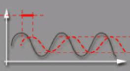 damped. While working in intermittent contact mode amplitude, topography, and phase images can be collected. An amplitude image is the raw data collected by the photodiode, given in volts. A topography image is created from the amplitude image, and is the distance the piezo traveled to return the amplitude to the set point. Phase images come from a secondary signal, in this case from the phase lag of the
cantilever relative to the drive signal.